Bore & Stroke
BORE & STROKE LAB
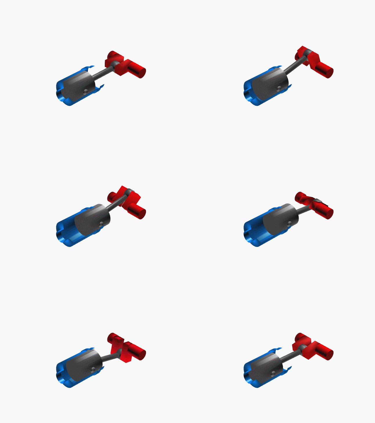
Internal Combustion Displacement Engine & Piston Stroke Kinematics Grid
NEW HORIZONS MISSION CONTROL • AUTOMOTIVE POWER LOGIC PROTOCOLS 2026
Engine Block Core
The Structural Host. The engine block serves as the rigid chassis for the internal reciprocating assembly. Its metallurgical integrity dictates the maximum allowable bore size through cylinder wall thickness tolerances.
Engineering: Modern blocks use aluminum alloys with cast-iron liners to balance thermal dissipation with structural rigidity.
- 🧱 Rigidity: Prevents vibration harmonics that ruin bore tolerances.
- 🌡️ Thermal: Manages localized heat flux from the combustion chamber.
Piston Velocity
Mean Piston Speed (MPS). As stroke increases, the distance a piston must travel per revolution rises. This elevates stress on the connecting rods and rings.
Physics: Excessive MPS leads to material fatigue. High-revving engines require shorter strokes to keep MPS within safe operational bounds.
- 🚀 Limit: The threshold where material failure becomes inevitable.
- ⏱️ Factor: Dictates the maximum redline of a design.
Rod/Stroke Ratio
The Angular Link. The relationship between the length of the connecting rod and the crankshaft stroke. This angle determines side-loading forces on the cylinder walls.
Performance: Higher ratios reduce piston side-thrust, leading to lower friction and increased longevity at high RPM.
- 📐 Geometry: Minimizing the rod angle during the power stroke.
- 🔗 Wear: Impacts cylinder wall longevity significantly.
Chamber Volume
Combustion Space (Vc). The volume remaining at Top Dead Center. This space, combined with the swept displacement, dictates the compression ratio.
Optimization: Precision machining of the head chamber volume is required to achieve specific compression targets for modern fuels.
- 🔥 Efficiency: Direct link to thermal expansion potential.
- 💎 Precision: Measured in cubic centimeters (cc).
Bore Spacing
Centroid Distances. The distance between the centers of adjacent cylinder bores. This dictates the maximum possible overbore before head gasket sealing failure occurs.
Constraint: The physical limit of cylinder wall thickness and cooling passage integrity.
- 📏 Grid: Essential for engine block design density.
- 🔲 Sealing: Limits the structural viability of the head gasket.
Valve Lift
Induction Displacement. The vertical distance the intake or exhaust valves travel from their seat. Coupled with bore size, this determines the total breathing capacity of the engine.
Correlation: Larger bores allow for larger valve diameters, exponentially increasing airflow potential at the same lift.
- 🌪️ Flow: Determines the potential volumetric efficiency.
- ⬆️ Lift: Translates cam lobe profile to mechanical opening.
Friction Mapping
Parasitic Drag (Pf). The power lost to friction between piston rings and the cylinder wall. Bore and stroke configuration directly determines the total surface area subject to this loss.
Dynamics: Lowering bore surface friction is the primary driver behind modern low-friction coatings and ring technologies.
- 📉 Losses: Directly detracts from net output torque.
- 🧪 Surface: Coated cylinder walls for reduction of drag.
Journal Dynamics
Bearing Load Path. The path of force from the piston to the crank journals. Stroke length determines the radius of the throw, directly affecting the peak load applied to crankshaft bearings.
Physics: Longer strokes create higher leverage but require beefier journals to manage the increased rotational stress.
- ⚙️ Force: Managing torque peaks during ignition.
- 🏋️ Stress: Defining journal diameters for bearing longevity.
Piston Profile
Crown Geometry. The shape of the piston head (flat, domed, or dished) is a vital variable in the combustion equation.
Function: Adjusting crown volume allows engineers to modify the final compression ratio without changing the cylinder head architecture.
- 🗻 Dome: Increases compression by shrinking total volume.
- 🥣 Dish: Lowers compression for forced induction.
Final Yield
Terminal Displacement. The culmination of bore, stroke, and cylinder count. This value represents the total air-pumping capacity of the internal combustion assembly.
Integration: All previous factors—rod ratio, compression, and chamber volume—work in tandem to determine how effectively this displacement generates usable mechanical energy.
- ✅ Synthesis: The final calculation engine output.
- 🏁 Performance: The baseline for all power-to-weight maps.
Master Bore & Stroke Dynamics
Dive deep into internal combustion physics. Explore how cylinder bore diameter and piston stroke length dictate an engine's torque characteristics, redline potential, and volumetric efficiency.
READ BORE & STROKE BLOGS